Custom Antenna Design Service
- 3G | LTE | NBioT | ATT | Verizon | Sprint
- Printed on YOUR PCB
- MODEMS and Base Stations
- Hand Held | Body Worn | OBD
- With or without GNSS bands
- Diversity Optimization & De-Correlation
- ISM (868 | 900 | 2400 | 5800)
- Printed on YOUR PCB
- WiFi – 802.11 | Zigbee – 802.15.4
- GPS | GNSS | BT & BTLE | 2.4 GHz
- UWB Linear Polarised
- RFID Coil Antennas
UWB Antennas
- Ultra Wide Band Antennas
- Circular polarised
- Ideal for pattern diversity
- Reduce multi-path effects
- Planar balun for low height restrictions
- OR center feed balun for best A/R
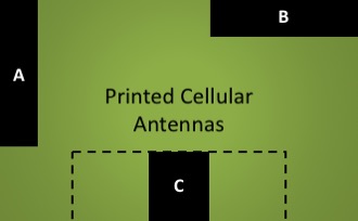
Custom Printed Cellular Antennas
Why use an expensive off the shelf cellular antenna? For a little NRE (non-recurring engineering) cost, RF LYNCS can print the antenna including matching components, in a 15 by 40 mm area illustrated in position A or B. The return loss and radiated efficiency performance will be similar to a COTS part using the same length of PCB. Yes, there are a few exceptions. Mainly small devices that require a custom 3D antenna to make the best use of the volume available, and NBioT where the antenna has to be larger due to the lowest operating frequency. Another location option is position C. Please ask for more information. If you are looking for cost reductions, then why not enquire? Contact RFLYNCS for state-of-the-art printed cellular solutions.
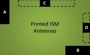
Custom ISM Antennas
RF LYNCS printed ISM antennas provide an opportunity to reduce substantially BOM cost. As illustrated, we primarily integrate two types of Omni-directional antennas on our customers PCBs: Printed F antenna (PFA), located at end of PCB in positions A or B; and printed magnetic field antenna (PMFA), located on a long edge of PCB in position C or D. Either of these antennas perform well compared to COTS parts when placed on the same physical size PCB. They have similar radiated efficiency, return loss, and peak gain. Call RF LYNCS now for a free consultation.
Wearable & Body Worn Devices
Wearable devices demand a unique antenna design approach. The physical size is relatively small, which limits both the radiating surface area and therefore bandwidth available. Also, the human body tends to detune the antenna and absorb a significant amount of radiated power. To help overcome these constraints, RF LYNCS wearable GPS, GNSS, WiFi, and BT solutions use a current driven antenna. This produces a strong magnetic near-field and is mainly unaffected by the human body. PMFA’s can be used to replace any COTS chip antenna part. They will take the same printed area and provide similar efficiency for an equivalent length PCB and the matching components cost less than 5c.

Antenna Impedance Matching
The purpose of the impedance matching circuit is to reduce the conducted power losses between the antenna and active electronics; and good transmission-lines design gives a low loss conducted RF signal path. To provide a robust solution, RFLYNCS takes the PCB materials, layer stack, component tolerances, matching topology losses and design margin into account.

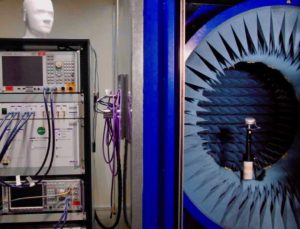
Radiated Antenna Testing
We evaluate the radiated antenna performance using an on-site MVG StarLab. The full spherical 3D near-field antenna test system helps to provide the insight required to design state-of-the-art antennas. To evaluate performance we measure efficiency, peak gain, azimuth, and elevation cuts. A 3D image is used to help orientate the axis. Explore our complete antenna testing service here.
Workflow
The activities to integrate either a COTS or custom antenna into your device follow a typical workflow show below. The appropriate steps can be selected as required:
1. System Analysis
- Schematic Review
- Mechanical constraints
- Environmental effects
- Performance requirement
- Antenna options (COTS v Custom)
- Performance cost-benefit
Deliverables
- Report including:
- COTS/custom antenna selection
- Design readiness
- Performance cost-benefit
- Milestone meeting
Inputs
- Schematic Diagram
- STEP files
- Use Case
- Sample devise as available
- Product Volume
- Target pricing
2. Design & Prototype Antenna
- Antenna Simulation
- Prototyping
- Initial Matching | Return Loss
- Measure radiation pattern | Efficiency
Deliverables
- Antenna Prototype
- Performance measurement report
- GERBER file (Custom antenna only)
- Milestone meeting
Inputs
- As above +
- Enclosure
3. Antenna Integration Support
- Transmission line design
- PCB GERBER review
Deliverables
- Final PCB Layout
- BOM
- Schematic Diagram
- Draft PCB layout
4. Antenna Impedance Matching
- Final Matching | Return Loss
- Measure radiation pattern | Efficiency
Deliverables
- Performance measurement report
Inputs
- Populated functional PCB
- Schematics & PCB GERBR files
5. Active Tests
- Cellular TRP | TIS
Deliverables
- Carrier compliance readiness
Inputs
- Populated operational PCB