About - StarLab Antenna Test System
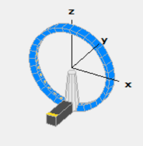
Our StarLab antenna test system provides full spherical gain and phase measurements. An arch of 15 scanning probes spaced every 22.5° surrounds the DUT (device under test) placed on a turntable. The turntable is rotated 180° around the Z-axis and the probes array can rotate over ± 11.25° in elevation (Y-axis), such that it positions the probes in offset locations. This over-sampling fills in the gaps between the probes, and we can select between 1.125° to 22.5° to resolution. The combined electronic scanning of the probes and mechanical elevation scanning allows fast and fully automated measurements. This means that full 3D radiation pattern measurements are performed rapidly compared to conventional single-probe systems.
Testing a Passive Antenna
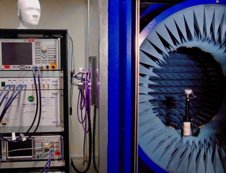
The antenna is placed on a turntable and connected to the signal source via a decoupled coaxial cable. We use a laser level to center the DUT to the arch probes for optimum accuracy.
Next, we open the measurement software and input the operating frequency range, oversampling resolution and diameter of DUT and select run. That’s it, the test system measures the antenna near-field pattern. Finally, we process the near-field data and convert it to far-field.
We can either send you a data file for use with our open source antenna pattern viewer or provide a test report. There are numerous ways to display the antenna pattern. However, most of our customer request 2D Cuts and radiated efficiency.
The test system is calibrated each year by the Microwave Vision Group (MVG) and we can supply a certificate of compliance. We confirm the calibration regularly using a selection of MVG ridge horns and dipoles.
Oversampling - Resolution
The accuracy of the StarLab measurement system is a function of frequency, the diameter of the antenna, and the test system sampling resolution. For example, the table inset shows that an azimuth and elevation sampling resolution of x4 oversampling (22.5°/4 = 5.6) meets ± 1.1 dB test accuracy over the frequency range 0.8GHz to 5 GHz. Note that with suitable calibration antennas the StarLab will work down to 0.6 GHz.
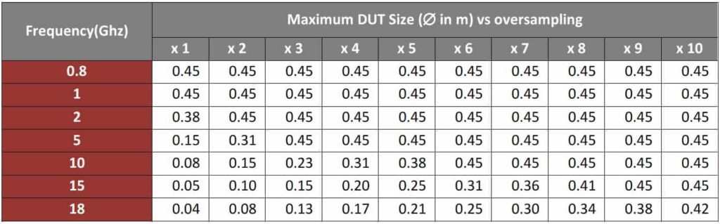
A higher oversampling resolution may be necessary for directional or beam forming antennas versus omni-directional and depends on the beam width. To maintain the peak gain accuracy, a beam width of 30° would require a minimum of 8 samples at 3.75° resolution to characterize the main beam lobe.
Peak Gain Accuracy
The MVG near field test system ‘peak gain’ accuracy is specified ‘without oversampling. RFLYNCS always oversamples at a minimum of x4 (5.25 degree resolution) and results in a peak gain accuracy better that +|- 0.6 dB.
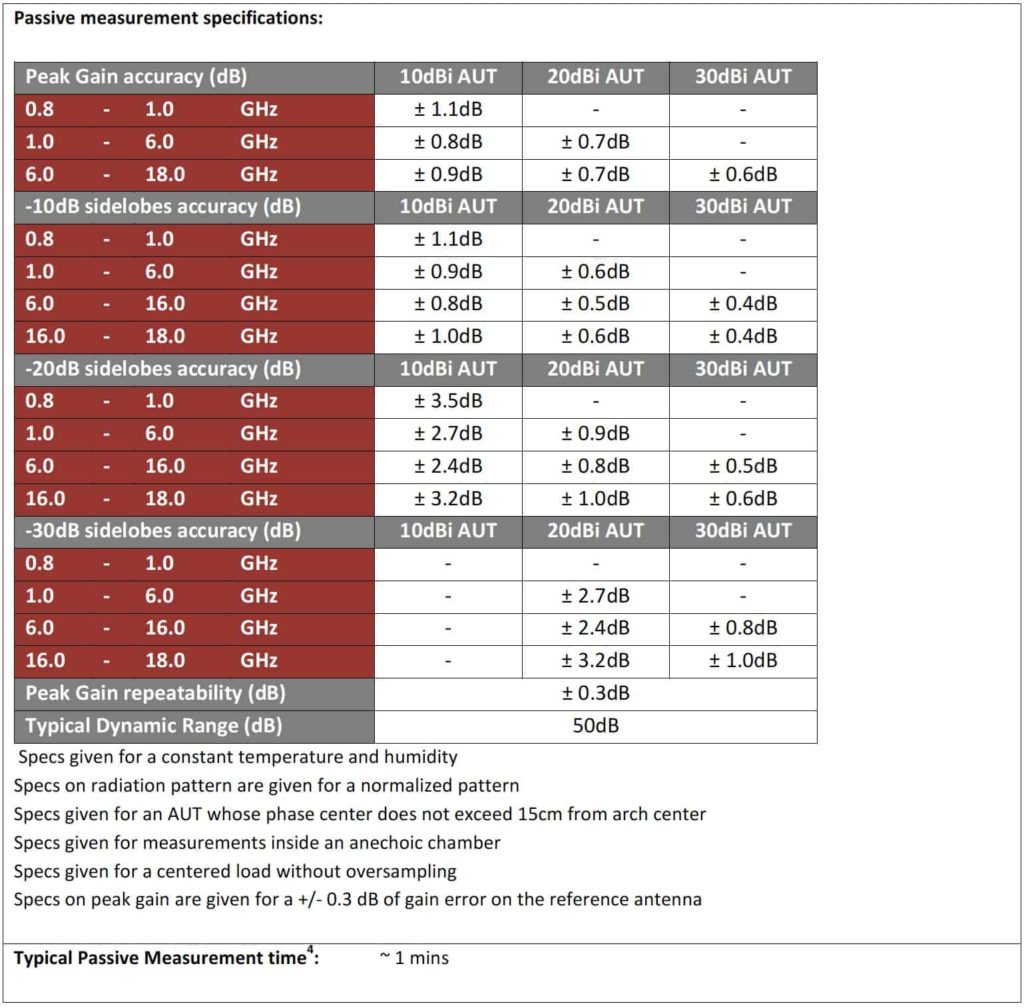
The full MVG near field anechoic test system performance specification can be found here.